|
How to mount your Mini on A Spit!
 |
| |
|
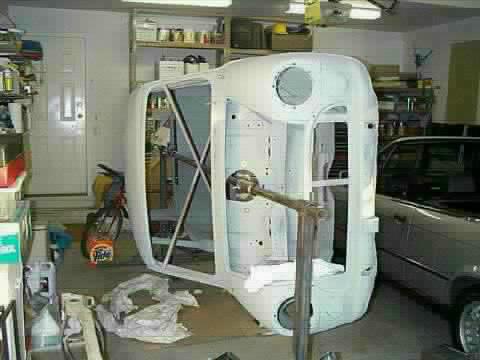
To make it easier to work on major restoration work, here is a few pictures
and measurements for putting together a rotissaire on which you can mount your Mini. As the cars usually rust from the bottom
up, life is a lot simpler when you can spin the car around to work on the bottom. This make welding, painting and mounting
all the fuel and brake lines a standup propostion, instead of lying on your back. |
|
| |
The stand is quite simple to build if you have a welder, some scrap steel and
a few nuts and bolts. You will need the following:
- 2 inch square steel tubing - 24 feet
- 2 inch round steel tubing - 3 feet
- 1 3/4 inch round steel tubing - 12 feet
- 1 1/4 inch angle iron - 4 feet
- 1 inch flat steel bar - 8 feet
- 9/16 x 2 1/2 bolts with nuts - 4
- 5/16 x 2 1/2 lots with nuts - 12
|
|
| |
 |
|
| |
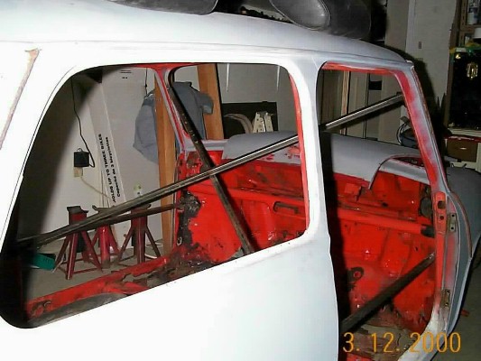
Before mounting the car on the rotissaire, it is a good idea to brace the car especially if you are removing the floorpan
or other main support parts of the body. For this you can use 1 1/4 inch square tubing. The tubing is welded across the door
openings fron the top of the rear storage bins to the door posts on each side. Then from the upper front windshield post to
the opposite side of the car attaching to the tubing just welded across the door opening. Then weld the tubing together in
the middle where they meet. This should keep the car from moving when any body parts are removed.
|
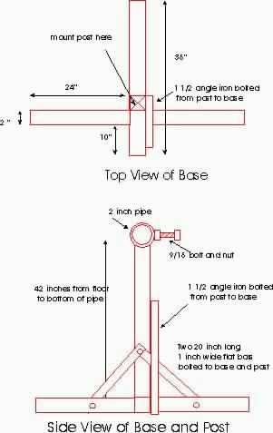
| The base is drawn out below. Sizes are approximate and can be adjusted, but this
is the size of the actual one in the picture. Use 2" Square Tubing for the Base and Post, 1" or 1 1/2 " flat bar for the side
supports, and 1 1/4" or 1 1/2" angle iron for the third support arm. The pipe on the top is a 2" inside diameter pipe with
a 9/16 nut welded over a hole drilled in the pipe. The bolt is then used to lock the car in postion as it pivots. A 12 foot
1 3/4 " outside diameter pipe will be run through the middle of the car and sits inside the pipe on the post. |
|
| |
 |
|
| |
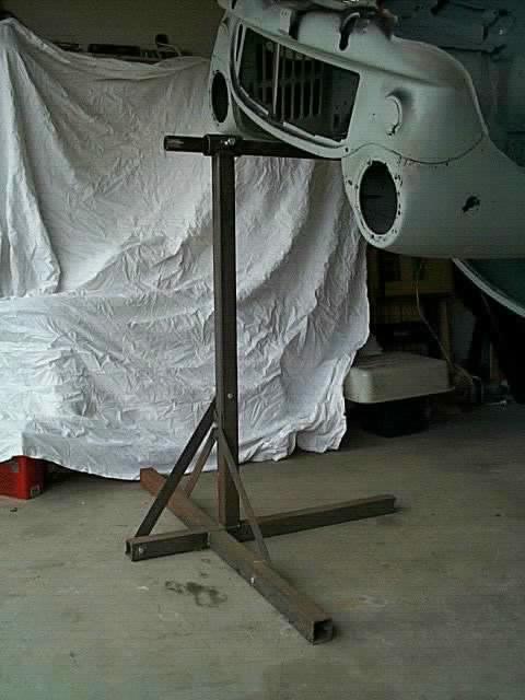
Here is a good shot of the completed base and post. You can see the braces
and also the pipe and nut welded to the top of the post. Check out the next pic for a closeup of the pipe and nut. |
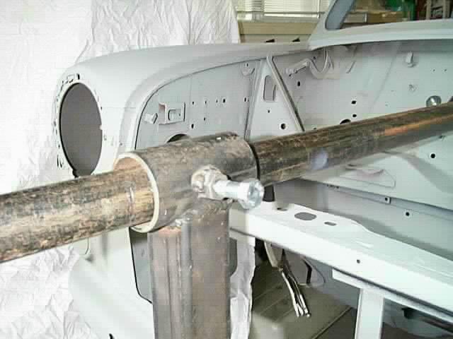
| This is a picture of the top of the post with the 2 inch ID tubing welded to the
top. A hole was drilled in the side of the pipe, the nut was bolted in place to hold it, and then welded to the pipe. This
allows the bolt to then be tightened down against the smaller pipe inside, locking the car in postion. I always use jackstands
to support the car in position as well as this ensures the car will not move. Safety first! |
|
| |
 |
|
| |
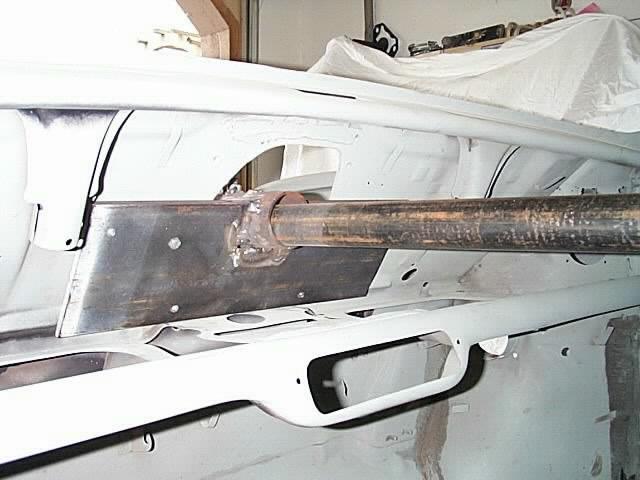
You can see the jackstand supporting the car on the right side of the picture.
You can also see the support tubing that has been welded inside to prevent any twisting of the body when the floor is removed.
The next thing you need is the plates that attach the pivot pipe to the car. |
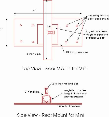
| This is the drawing of the rear mount. This bolts to the top of the parcel shelf
below the rear window. You can line it up, clamp it in place and then drill through existing holes in the shelf. I clamped
the mounts together, both front and rear, to make sure I had a good alignment, then tack welded everything in place. I then
removed them and did the final welding. It's not a pretty weld job, but it holds! |
|
| |
 |
| |
 |
|
| |
|
| |
 |
|
| |
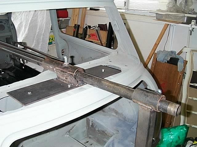
Here is the finished product. By having the nut and bolt setup here , this allows you to insert and remove the pivot
pipe as required, adjust the length out the fron and rear and lock it in place. The next steps shows the diagrams and
a few pictures of the front mount.
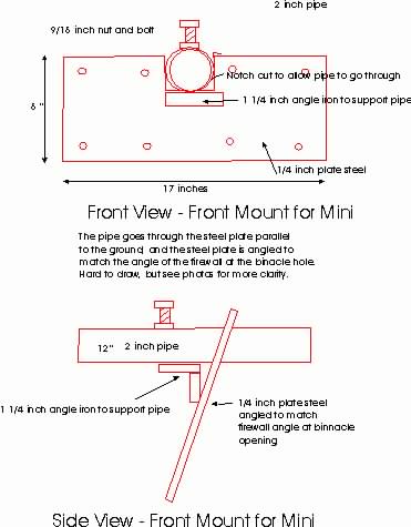
| This is the drawing of the front mount. This bolts to the firewall allowing the 2"
tubing to pass through the binnacle hole. The 1/4" plate steel is angled and bolted to the firewall (using existing holes),
after cutting out a 2 x 2 inch notch in the top. The pipe is then placed in the notch, and pivot pipe is fed through and aligned.
You can then tack weld the pipe in position and this ensures you have the correct angle. Remove the plate and tube and finish
the welding. Notice this also has a locking nut and bolt, and there is a small peice of angle iron added for extra support. |
|
| |
 |
|
| |
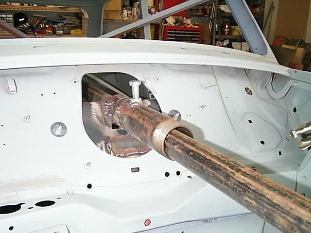
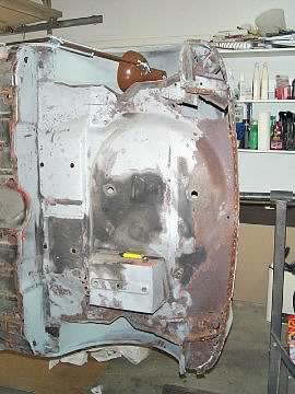
Here is the finished front mount. Notice the angle iron underneath the
pipe. This was welded in place to add more strength to the pipe support. By having the nut and bolt setup here , this allows
you to insert and remove the pivot pipe as required, adjust the length out the front and rear and lock it in place. The picture
below shows the front mount from the inside of the car. |
|
|
|
| |
 |
|
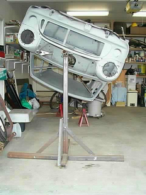
Here is a few shots of the car on the stand. I have found although it is not completely
balanced, I have no trouble adjusting the car by myself. |
|
| |
 |
|
| |
This shows how easy it is to work on the bottom of the car. Any questions
or comments please let me know...Hope this was useful....Mike |
|
| |
 |
Credit :Mike's Mini Info
|
|